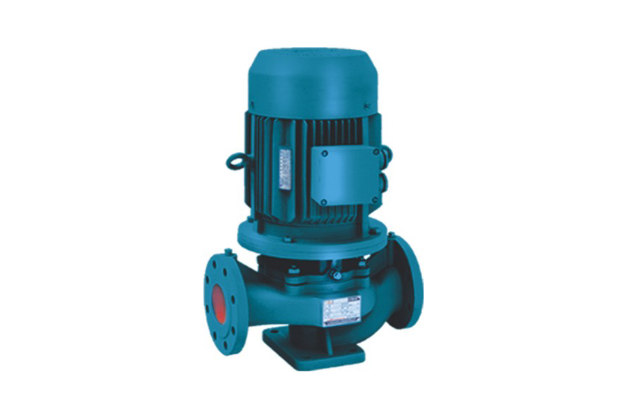
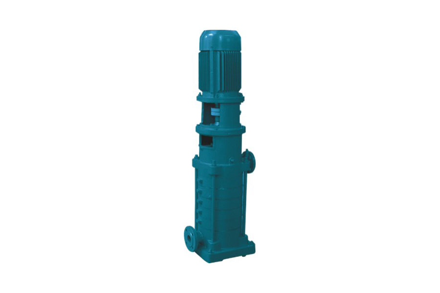
In industrial production, municipal construction and various fluid treatment scenarios, the BPL series vertical single-stage centrifugal pump undertakes key liquid transportation tasks. Its efficient and stable working performance comes from a unique and sophisticated work process, covering liquid suction, energy conversion and pressurization, and high-pressure liquid discharge. Each stage contains scientific design and engineering principles.
The starting point of the BPL series vertical single-stage centrifugal pump is the liquid suction process, and the core driving force of this process is centrifugal force. The motor equipped with the centrifugal pump drives the impeller to rotate rapidly at a high speed after starting. The high-speed rotation of the impeller is like a powerful "dryer", creating a special pressure environment in its central area. As the impeller blades quickly throw the surrounding liquid to the surroundings, the mass of the liquid at the center of the impeller decreases, and the pressure drops sharply, forming a significant low-pressure area. According to the basic principle of pressure balance in physics, a strong pressure difference is naturally formed between the atmospheric pressure and the low-pressure area in the center of the impeller. Under the action of this pressure difference, the external liquid is like being pushed by an invisible big hand, flowing continuously along the suction pipe to the center of the impeller, thus smoothly realizing the liquid suction. This suction mechanism based on centrifugal force and pressure difference is efficient and stable, providing a continuous source of liquid for the subsequent work of the centrifugal pump and ensuring the continuity of the entire conveying process.
When the liquid is successfully sucked into the impeller, it enters the critical energy conversion and pressurization stage. As one of the core components of the centrifugal pump, the impeller has carefully designed blades that present a specific twisted shape. When the impeller rotates at high speed, these specially shaped blades and the liquid engage in an "interaction" of energy transfer. As the impeller rotates, the blades continue to exert force on the liquid, pushing the liquid to flow inside the impeller. In this process, the motion state of the liquid continues to change, the speed is significantly increased, and the direction is continuously adjusted under the guidance of the blades. According to the law of conservation of energy, the work done by the blades on the liquid successfully transfers the mechanical energy input by the motor to the liquid, which greatly increases the kinetic energy of the liquid. At the same time, the design of the flow channel inside the impeller is also very particular. The shape of the flow channel is not a straight line that remains unchanged, but is designed to be contracted and guided according to the principles of fluid mechanics. As the liquid flows in this special flow channel, its flow space gradually narrows, the flow rate further accelerates, and the pressure gradually increases. After a series of actions by the impeller, the liquid that was originally in a low-pressure and low-speed state successfully achieved the transition to a high-pressure and high-speed state, which reserves sufficient energy for the subsequent discharge process and meets the strict requirements of different application scenarios for liquid pressure and flow rate.
After the impeller pressurizes the high-pressure and high-speed liquid, it immediately enters the pump casing, opening the last link of the entire conveying process - the stable discharge of high-pressure liquid. The pump casing is by no means a simple container. Its design contains profound engineering wisdom, especially the unique volute-shaped structure, which plays a vital role in this stage. When the high-speed and high-pressure liquid is thrown from the impeller into the volute, the flow channel inside the volute shows a trend of gradual expansion. According to the continuity equation of fluid mechanics, when the liquid enters the area where the flow channel gradually widens, the flow rate will slow down accordingly. In the process of reducing the flow rate, the kinetic energy contained in the liquid does not disappear, but is smoothly converted into pressure energy according to the law of conservation of energy, so that the pressure of the liquid is further increased. After this energy conversion process, the high-pressure liquid flows smoothly and orderly to the outlet of the pump under the careful guidance of the volute, and finally enters the subsequent delivery pipeline to complete the entire liquid delivery process. This high-pressure liquid discharge method based on the volute structure design not only ensures that the liquid can be output at a stable pressure and flow rate to meet the needs of various complex working conditions, but also minimizes energy loss and improves the overall working efficiency of the centrifugal pump.
The BPL series vertical single-stage centrifugal pump achieves liquid suction by cleverly utilizing centrifugal force, converts energy and pressurizes the liquid with the help of the special design of the impeller, and relies on the carefully designed pump casing structure to complete the stable discharge of high-pressure liquid. This series of closely coordinated and interlocking work processes constitutes the basis for its efficient and stable operation, and is also the key to the wide application of this product in many fields such as industry and municipal administration, and to provide reliable technical support for liquid delivery in various industries. By deeply understanding its working principle, users can better use and maintain this equipment to maximize its efficiency in actual work.

 English
 中文简体
中文简体







 Home
Home


